Tuesday, August 12, 2014
SUCCESS AT GDC MENENGAI

What makes up a success story in
the drilling industry may not be what makes up a success story in the
manufacturing industry. For example, in the drilling industry, there is only
one end product, a well that everyone is focused on. At GDC Menengai, I was
happy to see so many successful well that not only give the company hope for
the future, but also encourage the ever-toiling employees that their sweat
really counts at the end of the day.

Some of the moments I could see
investors being brought in to see some projects and would be amazed at the rate
at which some of these wells produce steam, I would look at them and see a
future where energy shortage is something past our generation.
Indeed, the success at GDC
Menengai crater is something to write far and wide about, megawatts here, there…and
there, to infinity.
Day 7 11/2/2014: ROTARY EQUIPMENT
On this day there was this
problem with the rotary table drive shaft that we had to attend to. The drive
coupling had a rubber grease covering that burst hence was subjected to high
friction and had been eaten away so much that the metal loss lead to noise and
vibrations that could be audible.
 |
| The Rotary Table |
That is the shaft from the DC
motor to the Rotary table gear box-a set of bevel gears that drive the drill
string via a Kelly and master bushing. The rotary table has two main functions,
to rotate and give torque to the drill bit and while tripping in and out-it
suspends the weight of the drill string (using slips) to allow connection and
disconnection of pipes and collars. The DC motor driving the rotary table is
controlled by adjusting current to it from the drillers console to vary its
speed depending on the formation type, bit size and many other factors. When
opened, it is a steel box with a ball-type bearing assembly fitting into a huge
diameter housing inside the frame. There are also the master bushings and a
turn table fitted with a large diameter ring gear that mates with the bevel
gear to change the horizontally rotating motor motion into vertical motion.
There are seals in the system to ensure oil does not leak thus creating a closed
oil sump for lubrication. I remember having the duty of
monitoring this oil level by measuring it with a dip stick and adding it if it
fell below the required level. Normally, though heavy, the rotary table unit is
very easy to remove and I even remember when we removed it as the shaft had to
be taken to NMC for machining.
 |
| The kelly bushing in place |
 |
| Master Bushing on the Rotary Table |
 |
| Swivel and kelly hose |
 |
| Making a connection with the hydraulic cathead |
Something to note with the rotary
table drive mechanism that I had to draw in my notebook was the centrifugal
motor before it. Seemingly, that AC centrifugal motor has to run before the
main DC motor as it has to suck in large volumes of air to the DC motor so as
to cool it down.
Also, I was told by Chris who was
in charge of electrical systems at Rig 2 that DC motors are prone to create
sparks so the cooling air also picks up and extinguishes these sparks as it
blows around while cooling the motor windings. To further prevent fires in this
area, the air is supposed to be clean hence the trunking that draws in fresh
air from a safe area.
 |
| Slips holding up the drill string |
The master bushing is the rugged
steel cylinder locked into the turn table with a center tapered middle section
that fits very well with the bowls that in turn have a taper to match the one
on slips. It was amazing how the two just clicked into each other to hold the
pipes during trip in and out while I was at Rig 4 in my last week.
On top of the master bushing, it
had to interface with the Kelly bushing that has hexagonal slots to match the Kelly
profile hence help the rotary table drive the drill string. Kelly bushings have
pin drive mechanisms on edges with drive pins that fit into drive holes on the
master bushing.
As the driller turns the rotary
table clockwise, it is attached to the Kelly which has a string of pipes below
it, couples with collars, stabilizers, bit subs etc. all the way to the drill
bit. As the drilling bit goes deeper into the formation, the Kelly slides
between the Kelly bushing rollers allowing the bit to remain in contact with
the formation and continue cutting. Once the bit has cut around roughly 10m, it
becomes necessary to add a pipe so the driller raises the stem until the connection
is about a meter above the rotary table so that the drill crew sets the slips
to hold the weight of the stem while the crew disconnect the Kelly to add a new
section of pipe.
While adding extra drill pipe,
the weight of the drill pipe is normally suspended to prevent the whole string
from falling into the well and secure the pipe so that the new joint can be
fitted and tightened. To secure the pipe, a pair of slips is put between the
pipe and bowl so that the weight of the drill pipe forces the back of the slips
tightly onto the bowl, this force acts as a wedge hence locks the pipe tight in
place.
A new pipe can then be added, tightened,
pipes raised, slips removed and string lowered back into the well. Some of the
crew members actually called the bowls-bushings and I was told it is still
correct to refer to them that way. Above the Kelly, is a swivel and rotary
hose. The swivel has a bail-just like a bucket handle that hangs from the hook
on the travelling block. The swivel allow the attached Kelly and drill string
to rotate, at the same time the rotary hose conducts drilling mud into a curved
pipe called the gooseneck which attaches to the swivel and carries mud to the
swivel via a wash pipe. The rotary hose is flexible…you can’t even believe it
is steel reinforced. Just don’t let it fall on you as it can break your back.
That is what Mr. Oyomno, our supervisor told me while insisting on the
importance of PPE’s.
The wash-pipe is a high pressure
passage way in the swivel that conducts high pressure drilling mud into the Kelly
and drill string. There are very strong main thrust bearings that support the
weight of the whole drill string as it rotates.
 |
| Stands of pipe |
I remember on this afternoon we
really worked a lot on the dismantling of compressor pipes as we disengaged
them using big harmers and arranged them aside. This was a very tiresome
exercise although it was a great muscle building exercise….finally, it was 4 o’clock,
tea time, after which we changed our clothes and our van arrived to take us to
town.
 |
| Drill collar-spiral grooved type |
Day 6 : 10/2/2014-DRAWWORKS BRAKE SYSTEM

Of course you can see where am
heading to….brakes. Starting with the eddy current brakes that are normally
referred to as the auxiliary brake system that is applied while the travelling
block is being lowered to just reduce the speed of descent so that the main
mechanical brakes can be applied at minimum effort. This helps to ensure that
the main brakes do not wear off that fast as this would shorten their working
life and increase the expenses of replacing the brake pads now and then. I
remember on Rig 2, we only replaced the brake pads once and as I went round the
rigs, there was no where we did that again. On the side of the eddy current
brake was a coupling handle that we always ensured was locked in place and that
the eddy current brake water cooling system was always running to dissipate the
heat generated.
 |
| Replacing brake pads |
Then you could be wondering how
the eddy current brake (ECB) works…it just supplies a series of coils with a
strong current that creates a magnetic flux. The shaft attached to the
drawworks has a large steel drum that rotates around the coils cutting through
the magnetic field such that it acts like the opposing pole of a magnet
creating a drag resistance to rotation….slowing down the drum thus allowing the
best moment to apply the main brakes. Normally, the heat generated is so much hence
the need for water cooling.
One can actually hear a lot of
noise as the clutch release valve vents out air while doing the fast
disconnection of pads from the clutch drum. This noise could really shock me to
y nerves on the first few days before I got used to it.
The main brake system is a
hydraulically operated disk brake type with double brake pads and an open-close
brake tong. Seeing the hydraulic lines running all the way to the HPU made me
remember my hydraulics system class work as I appreciated its application here.
The drum also had an anti-clash system that I was taught about too…just a
safety system to ensure the crown block did not hit the top of the mast and the
drilling line did not excessively fill the drum to an extend of blocking it. This
crown saver system works such that when actuated, the crown toggle valve on the
drawworks sends an air signal to an air operated pilot valve on the front of
the hydraulic manifold on the HPU (Hydraulic Power Unit) so that the valve
caused 2-position,4-way valves in the manifold to exhaust their pilots, shift
and dump pressure from the emergency calipers and holding onto the drum thus
preventing the travelling block from striking the crown.
Some of the defects we checked on
the chain with Ndereba at GDC Rig 2 were tension of the chain, missing end-plates
and wear or damage on the chains. He told me about the small lubrication pump
that constantly sprays oil onto the chains to keep the lubricated and cooled.
 |
| Working on the Chain links |
Day 5 PART 2: DRAWWORKS
 |
| The Drawworks |
Next are the components on the rig floor starting with the noisiest part- the drawworks. It’s a JC-70D type and any one who did science in primary school would describe it as a large winch or drum with a large spool of drilling line wrapped around it. While standing close to it, you can easily understand how it works, driven by two massive DC motors each 800 kW via an air clutch and drive chain mechanism which you can hear whenever the driller activates control and releases the brake.
|
| The leBus Grooves on the Drawworks and the Brake System on the right |
Even more amazing is the automatic reeling and unreeling of drilling line as the travelling block is raised and lowered-of course I could understand how the leBus grooving system does all this for even multiple rolls of the drilling line and it would still arrange it so neatly on the drum. The function of the drawworks is to deliver the drill bit to and from its area of operation and to transmit the loads to the rig structure. To enable this, the drilling line is attached to an anchor on the drum on which the wire is spooled, and the wire is fed from a storage spool that I could see on the ground just behind the rig….of course the spool contains enough wire to last for long because I don’t remember there being a shortage of drilling wire that necessitated any pulling in of more wire from the spool. The wire from the spool is fed to the DLA-Dead Line anchor, then to the “fast line” of the crown block at the top of the derrick where it goes through a series of pulley sheaves and down through the travelling block sheaves before passing back to the crown again and onto the drawworks drum and once enough wire is spooled around the system, the rest is securely clamped to the DLA. The “fast line” is subjected to most wear and it’s the one I concentrated on most while lubricating.
 |
| As we worked on chain repairs |
For its working, the drawworks has two DC motors fitted with toothed couplings connected to sprockets that use chains to drive even larger sprockets for more torque. The driven sprockets are bolted onto the drive shaft and do not rotate till the high or low gears are engaged when the driller selects the required clutch setting while raising the travelling block and drill string. Basically, normal operations involved engaging clutches and motors for any hoisting operation and disengaging to allow a free fall and braking to control gravity falling of loads. Of course I had learnt about the pneumatic clutches and this is the first place I saw it being applied…..ever heard of fawick pneumatic clutches…..same principle.
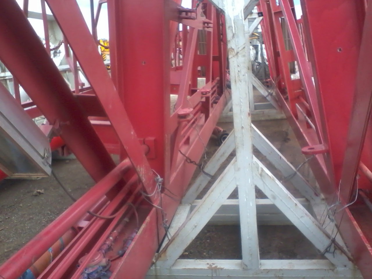
Day 5 PART 1 7/2/2014: The Substructure
 |
| The Substructure |
The next part we looked at was
the substructure and as Mr. Nyaga explained to me, I can just describe it as a
rugged system of beams….in this case, the whole of the green part that supports
the mast, the rig floor and provides a platform for installation of the other
mechanical and electrical systems that are on the floor. It must be high enough
just to accommodate the BOP stack below it. And while he was explaining this,
somebody came and tricked me at first that he was looking for a key to open the
V-door and they had to explain to me that the V-door is not really a door….that
sounds funny, its just a controlled access route used by crew members to hoist
pipe and equipment from the catwalk up the pipe ramp to the rig floor by
pulling using the air hoist…which I really liked to operate. I remember while
at Rig 4, I was nearly overpowered by a drill pipe while it was being raised
and I had to trap it with a piece of rope but thanks to the unity of fellow
crew members at GDC, the helped me to do it safely.
The exact type of substructure is
a DZ450 that puts the drilling floor at about 10.5 m.


Day 4: 6/2/2014 Rig Orientation at GDC Rig 2-The mast
Of course I know that you too
would like to know parts of the rig. In this case, when I asked, I was told
that the drilling rigs at GDC are all from China, model type ZJ70D. The ZJ70D
is an SCR DC driven drilling rig with a maximum depth of 7 km. However, after
staying here for sometime I came to a conclusion that it the hardware is
china-made, but the brains are purely German technology.
 |
| The Mast |
Right off by just looking at the
rig I was shown the mast and derrick assembly. This will be what you see first
whenever you see a rig from far. I overheard some new guys who had never seen
it before asking what kind of “booster” that was….ha ha ha. The mast is a
strong massive tower that supports other equipment like the travelling block
and the hook. The mast stands independently on the rig floor and is a welded
structure tall enough to allow the drilling crew to set up the drill pipes and
other tubulars like drill collars during a trip out. It also has to be tall
enough to allow the driller to raise the travelling block above the monkey
board so that the derrick man can dislodge and lodge on pipes during POOH and
tripping in respectively.
 |
| The A-frame |
 |
| The mast before being carried away |
The mast on the ZJ70D is the
JJ450-5 type which supports a maximum swivel load of 4500 kN and extends to
45.5 m. It is equipped with a step wise climbing mechanism surrounded by a
casing like anti drop mesh of rails for safety and also has many attachments to
hold the slings for the safety gear.
I do remember very well my last
moment at GDC Rig 4 where we were pulling out 3 joint stands of drill pipes in
the rain and arranging them on the floor held by fingers, while tripping out,
so as to change the drill bit. Tripping
pipe in stands is much faster as it helps hasten the tripping process.
Those of us who do not know the
monkey board-is the platform up on the mast where the derrick man works. The
walkaround or watertable is the platform that permits access to the crown block
at the top of the mast. The crown block is the uppermost system of pulleys
where the drilling wire passes and I remember going there once to grease……very
epic experience. The safety at GDC is very paramount as policies are in place
to ensure no one is injured. Use of safety gear for all height operations is
mandatory and the drilling supervisor and your fellow team members have a
responsibility to follow up and ensure you are safe.
Day 3 5/2/2014
I know am supposed to take you
through my day three but before that…..today I just did my CAT 1 on Computer
Controlled Manufacturing (CCM). I had a rather smooth time explaining the use
of pneumatic valves in speed control especially thanks to the knowledge passed
to me by Mr. Nyaga, one of the best technicians at GDC Rig 2 who gave me a lot
of hands-on knowledge on Rig Mechanical systems from hydraulic, pneumatic and
Structural Mechanics…..very beneficial information that I bet I would not have
found anywhere. And how is speed control applied on pneumatic systems on the
Rig?
The pneumatic system does the
braking of the drawworks while doing POOH and RIH operations
both automatically using the two protective limit and safety devices,
and by the driller applying brakes. The whole system is pneumatically activated
and I remember interpreting the circuits at the Maintenance Cabin, Wow!
Ok, this is not the day for this,
On day three was arrival day at the field, Menengai. Here comes the good
part…..our Van. I do appreciate on behalf of my fellow interns, the transport
that the company gave us. This was the best part of this hospitality at GDC, a
company van with a designated driver just for the attachees was just awesome.
We really appreciate Godana, our driver from day 1, for being very kind
accepting the challenge despite the fact that he had other errands to run, like
being the Head of Camp at Menengai. So, to cut it short, he picked us up at 7am
from Generation house parking to Menengai, more specifically dropped us at Rig
2 on his way to the camp.
On this day, we were all new and
knew nothing about drilling Rigs and so we asked many questions as we drove
past Kabarak, into Menengai, Barrier and even had more questions when we saw
the “booster-like” things for the first time. We went past Rig 1 and could see
Rig 3, Rig 4 before we alighted at Rig 2 and were handed over to Mr. Too, the Rig
2 Maintenance Engineer. Of course I had done a bit of research and watched as
many videos as possible about drilling rigs and so I was the one helping answer
some questions that I could while Mr. Nyaga helped us understand more.

So, on being welcome here, we
just got to work. Rig 2 was on Rig down, i.e being dismantled in readiness to
be transported to another site that was being prepared. Wow, Mr. Nyaga told us
that we were the luckiest attachees because we would gain maximum experience as
we would see every part of the Rig and this didn't make sense till later….we
really learnt a lot.
So Mr. Too gave us our first
task, stating clearly off course that at the Rig we would learn more by
experience and doing a lot rather than just watching people do things so we
were greatly encouraged. Our task for most of that day was transferring items
from a KOOMEY to a store cabin for better storage and arrangement. Some of the
items we transferred included Generator and Compressor filters for oil and
fuel, Valves and transducers mostly
Rexroth Control valves…yeah German Technology running Chinese Rigs; Motors etc.
 |
| The SKF induction heater |
I remember transferring this SKF
induction heater from the KOOMEY to the store. You may be wondering just what
this is…..it’s used to insert bearings for example where the bearing is
supposed to have a tight fit so its slightly smaller, so you use this heater to
expand it a bit before you do the fitting.
We all did some good teamwork
here and all parts were well arranged in the store. Unfortunately, it was too
late for this day and as we slowly took our 4 o’clock tea which I still miss
till today, we got to know even more people at the rig as we waited for Godana
to pick us.
Mr. Nyaga promised to do a proper
orientation for us on the next day and as we left for Nakuru town, we looked
forward to the next day with a lot of enthusiasm.
Subscribe to:
Posts (Atom)